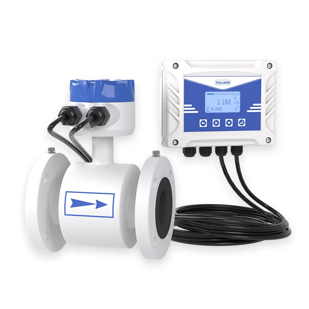
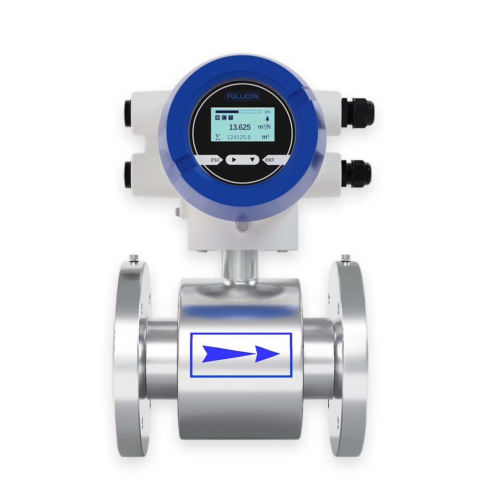
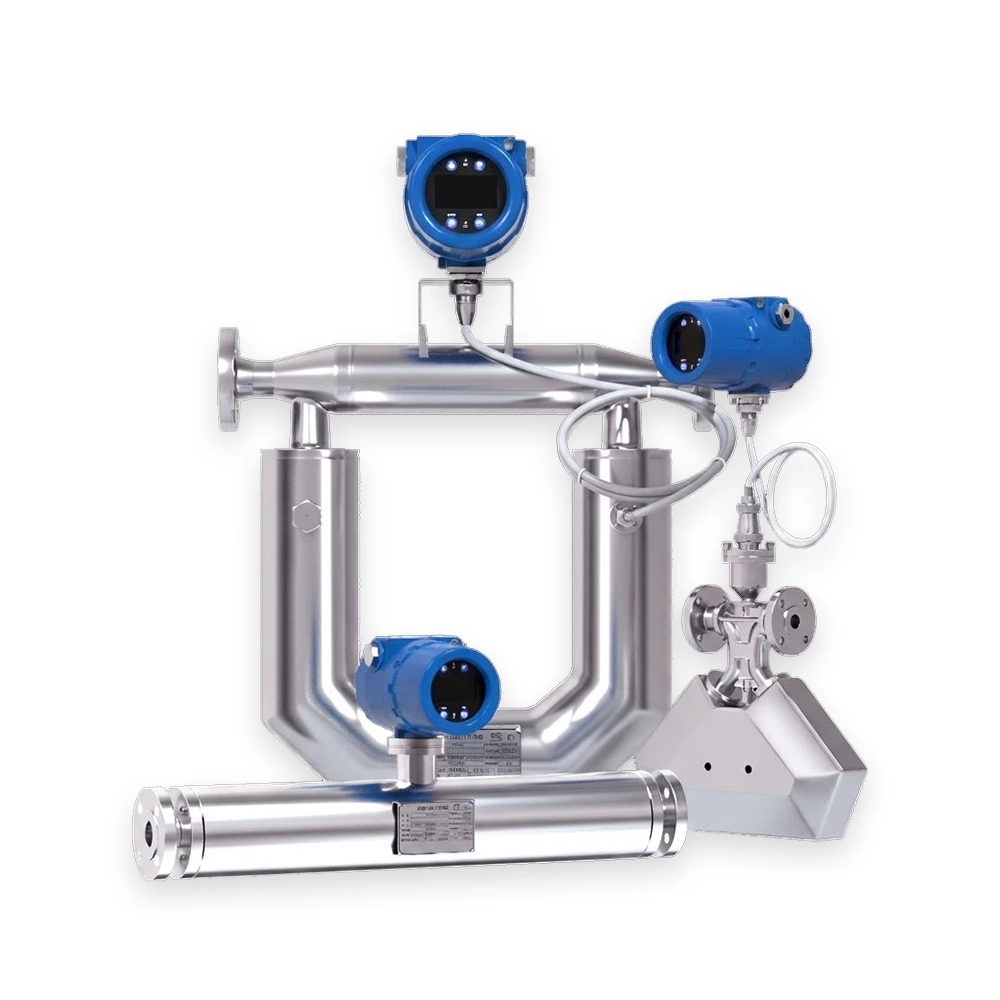
The electromagnetic flowmeter is designed based on Faraday’s law of electromagnetic induction and is used for direct measurement of conductive liquid flow in closed pipelines. It provides high measurement accuracy, stable performance, and long-term reliability for industrial process control.
The instrument supports multiple signal outputs, including standard current output (4–20 mA), pulse output, and RS485 digital communication, enabling seamless integration with control systems for monitoring, data recording, adjustment, and automation control.
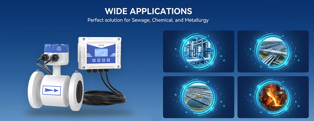
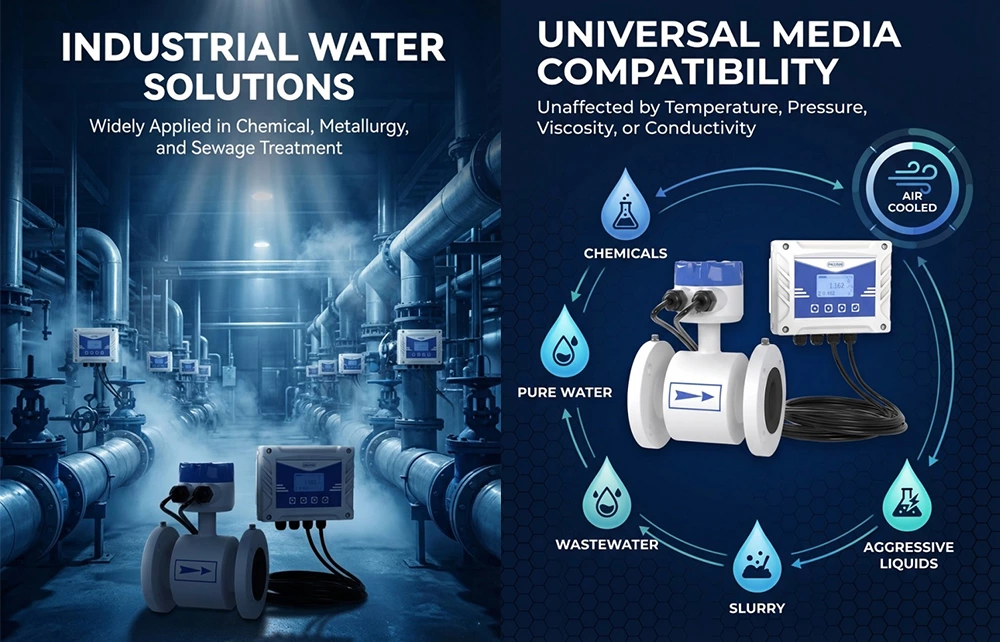
With its robust structure and wide adaptability, the electromagnetic flowmeter is suitable for a broad range of applications, including water supply and wastewater treatment, chemical processing, coal and mining industries, environmental protection, light textile, metallurgy, and papermaking, making it an ideal solution for modern industrial flow measurement.
Designed based on Faraday’s electromagnetic induction principle for accurate flow measurement of conductive liquids
No moving parts, ensuring minimal maintenance and long service life
Wide measuring range with stable and repeatable performance
Supports multiple output signals, including 4–20 mA, pulse output, and RS485 communication
Bidirectional flow measurement supported
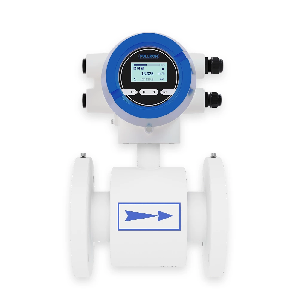
Compact structure with easy installation and operation
Suitable for harsh industrial environments with strong anti-interference capability

The operating principle of the electromagnetic flowmeter is based on Faraday's law of electromagnetic induction. The two electromagnetic coils at the upper and lower ends, as shown in Figure 1, generate a constant or alternating magnetic field. When the conductive medium flows through the electromagnetic flowmeter, the induced electromotive force can be detected between the left and right electrodes on the wall of the flowmeter tube. The magnitude of the induced electromotive force is proportional to the electrically conductive medium flow rate, the magnetic induction density of the magnetic field, and the width of the conductor (the inner diameter of the flowmeter measuring tube), and the flow rate of the medium can be obtained by calculation. The induced electromotive force equation is as follows:
E=K×B×V×D
Where: E-Induced electromotive force
K-Meter constant
B-Magnetic induction density
V-Average flow speed in the cross-section of the measuring tube
D-Inner diameter of measuring tube
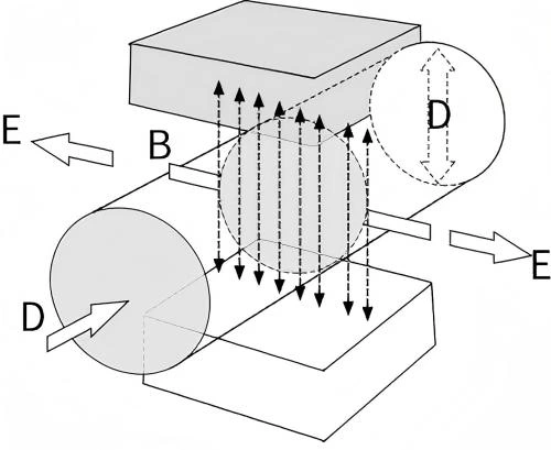
When measuring the flow, the fluid flows through a magnetic field which is perpendicular to the flow direction. The flow of conductive fluid induces a potential proportional to the average flow velocity, thus requiring the conductivity of the measured flowing liquid to be higher than the minimum conductivity. The induced voltage signal is detected by two electrodes and transmitted to the converter via a cable. After a series of analog and digital signal processing, the accumulated flow and real-time flow are displayed on the display of the converter.
Water supply and wastewater treatment
Chemical and petrochemical industries
Coal, mining, and slurry measurement
Environmental protection and water monitoring projects
Metallurgy and steel plants
Papermaking and pulp processing
Food and beverage industry (conductive liquids only)
Light textile and dyeing industries