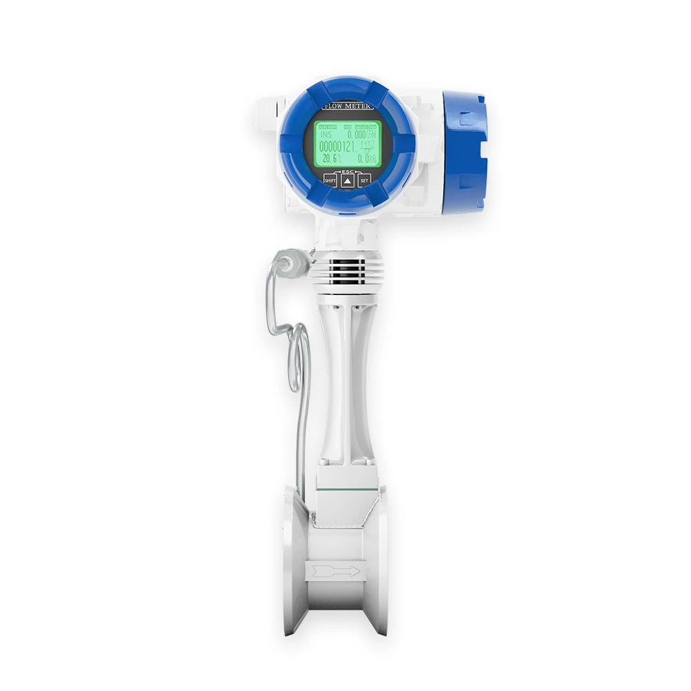
The Vortex Flow Meter is a velocity-type flow measuring instrument designed based on the Kármán vortex principle. It is widely used for accurate flow measurement and process control of steam, gas, and low-viscosity liquids in industrial pipelines.
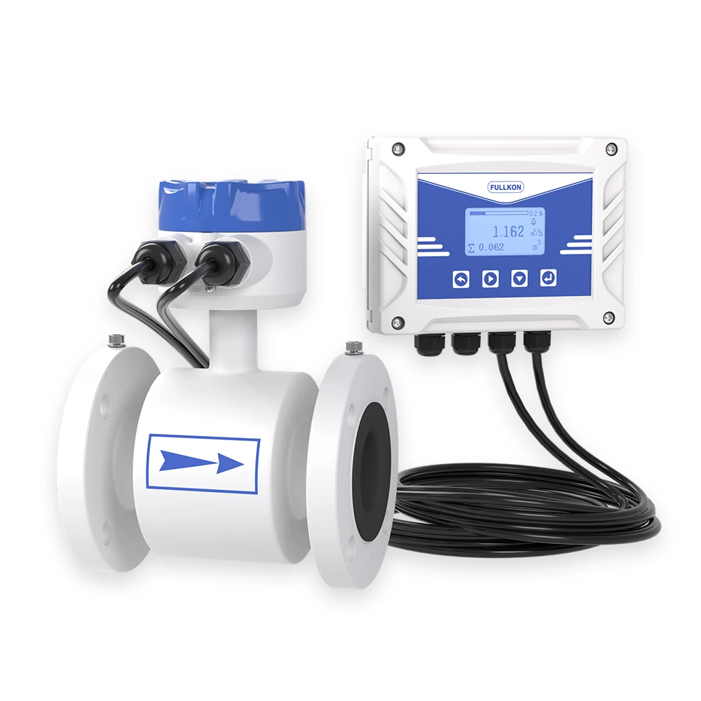
The meter can be configured to measure flow, temperature, and pressure simultaneously, providing both instantaneous and totalized flow data. It supports multiple output options including pulse signal, 4–20 mA analog output, and RS485 communication with Modbus RTU protocol. Optional GPRS communication enables remote data transmission and monitoring.
With no moving parts and a robust mechanical structure, the vortex flow meter offers excellent long-term stability, low maintenance requirements, and strong resistance to vibration and electrical interference. It is an ideal solution for energy metering and industrial automation applications.
Kármán Vortex Measuring Principle
Stable and proven technology for steam, gas, and liquid flow measurement.
Wide Media Compatibility
Suitable for saturated steam, superheated steam, compressed air, industrial gases, water, and low-viscosity liquids.
Multi-Parameter Measurement
Supports flow, temperature, and pressure measurement for energy and mass flow calculation.
Multiple Output Options
Pulse output, 4–20 mA analog signal, RS485 communication (Modbus RTU), optional GPRS.
High Reliability & Stability
No moving parts, resistant to vibration, pressure fluctuation, and electrical interference.
Low Maintenance Design
Long service life with minimal maintenance requirements.
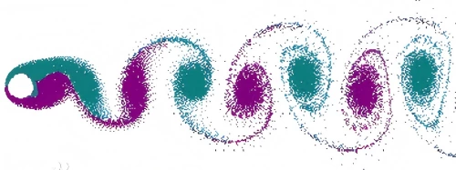
The vortex flow meter works on the principle of the generated vortex and the relation between vortex and flow by the theory of Karman and Strouhal, which specializes in the measurement of steam, gas, and liquid of lower viscosity. As shown in the below illustration, the medium flows through the bluff body, and then vortex is generated, vortices are alternately formed on both sides with opposite directions of rotation, Vortices frequency is directly proportional to medium velocity. Through the number of vortices that are measured by the sensor head, medium velocity is calculated, plus flow meter diameter and the final volume flow comes out.
Computational formula is as follows:
F=St*V/md ………………………………………………… Formula 1
Q=3600*F/K ………………………………………………… Formula 2
M=Q*ρ ……………………………………………………… Formula 3
Among Formula:
F…… Fluid flow through the bluff body generates the frequency of vortex (Unit: Hz)
St… Strouhal constant ( zero dimension )
V……Mean velocity of fluid inside the pipeline (Unit: m/s)
m……The ratio between the Lune Circulation area of the bluff body at both sides and cross-sectional area ( Unit: zero dimension )
d…… The upstream face width of the bluff body inside the vortex flow meter Unit: m )
D…… Inside diameter (ID) of vortex flow meter (Unit: m )
Q…… Instantaneous volume flow (Unit: m 3 / h )
K…… Instrument coefficient of vortex flow meter (Unit: pulses / m 3 )
M…… Instantaneous mass flow (Unit: kg/ h )
ρ……. Fluid density (Unit: kg/ m 3 )
Note: vortex flow meter "K" coefficient corresponds with one diameter, the exact ''K" value
should be calibrated in practice. Viz. one cubic meter fluid through sensor output numbers of pulse under working conditions.
District heating and energy metering
Gas and compressed air systems
Chemical and pharmaceutical industries
Environmental protection and emissions monitoring
Metallurgy and steel plants
Textile and paper industries
Water supply and drainage systems