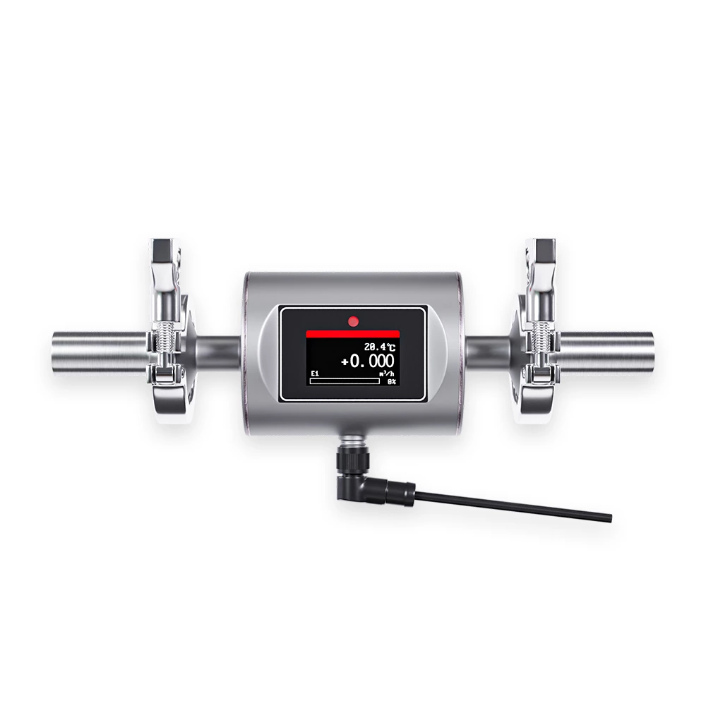
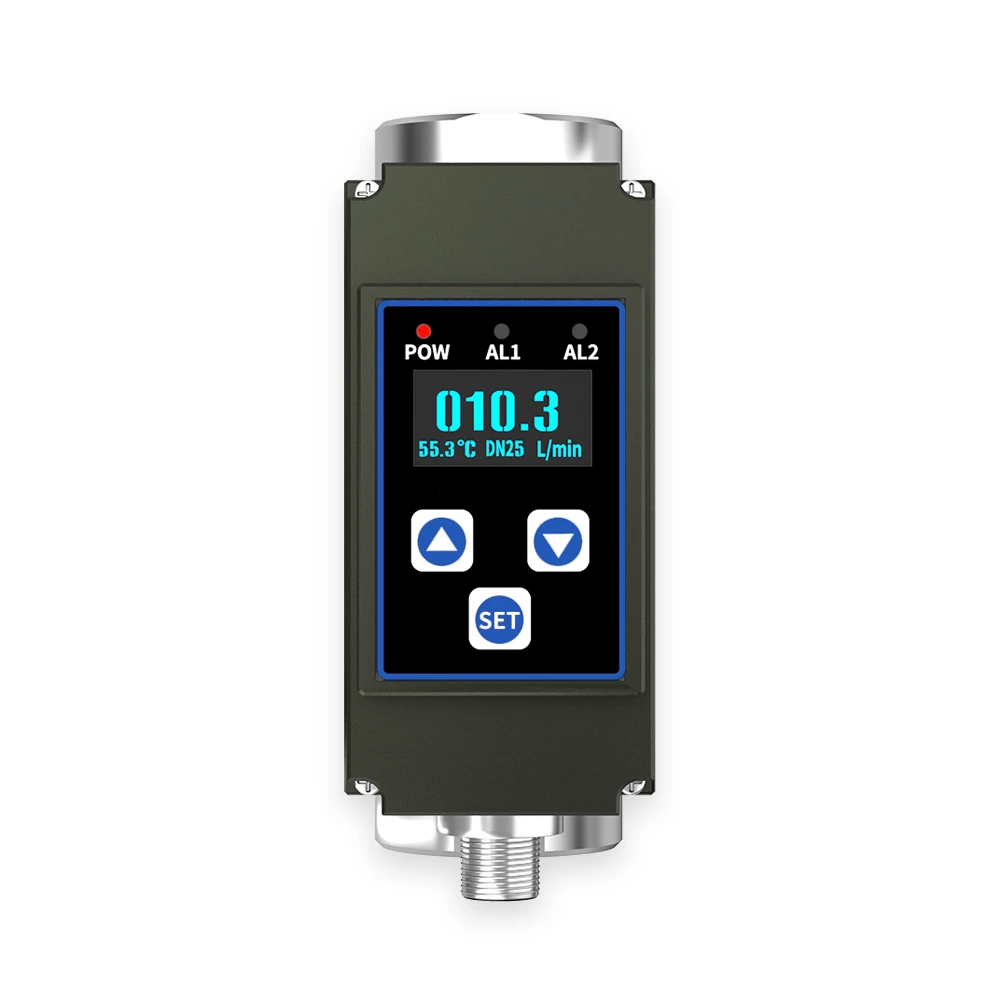
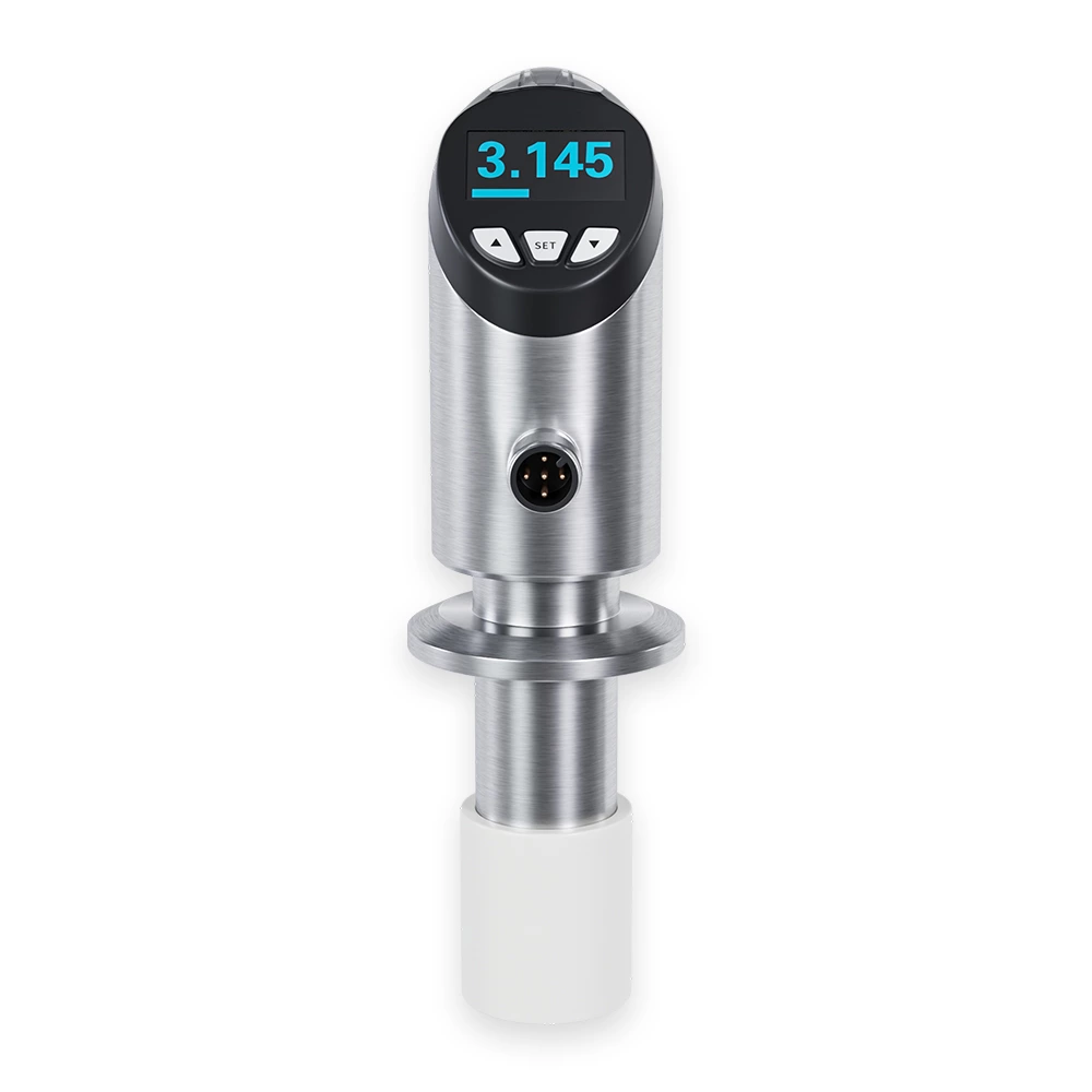
The Compact Electromagnetic Flowmeter integrates the traditional magmeter’s sensor and transmitter into a single, compact unit. Designed for flexible installation, it features infrared remote control for easy commissioning and configuration. The flowmeter is suitable for measuring the volumetric flow of conductive liquids with a minimum conductivity of 2 μS/cm. Its inductive measurement principle ensures reliable, accurate flow readings across various industries.
Fluid Property Immunity: Accurate measurement unaffected by fluid density, viscosity, temperature, pressure, or conductivity changes
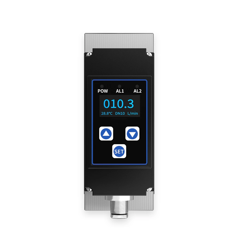
Temperature Monitoring: Built-in temperature measurement with signal output
Single-Mold Structure: Electrode and liner formed in a single molding process for enhanced stability and reliability
Digital Processing: Fully digital signal processing ensures high accuracy, broad measurement range, and strong anti-interference capability
Wide Voltage Range: Ultra-low EMI power supply with wide input voltage range and high EMI resistance
High-Performance Processor: ARM Cortex-M4 32-bit processor with 24-bit ADC for fast, precise, and low-power operation; programmable low-frequency rectangular wave excitation enhances measurement stability
Reliable Circuit Design: SMD components and surface-mount technology (SMT) for improved reliability
Customizable Range: Measurement range can be adjusted online according to user requirements
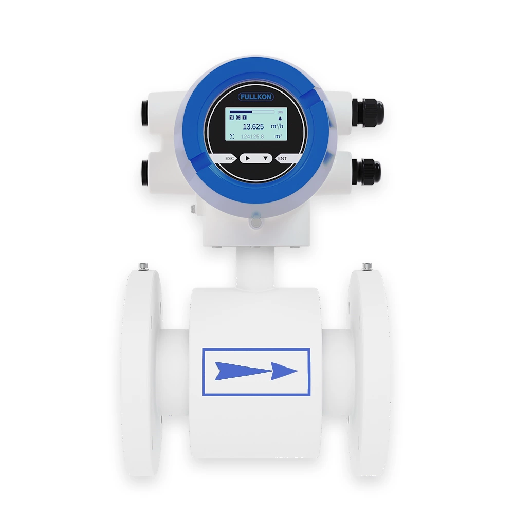
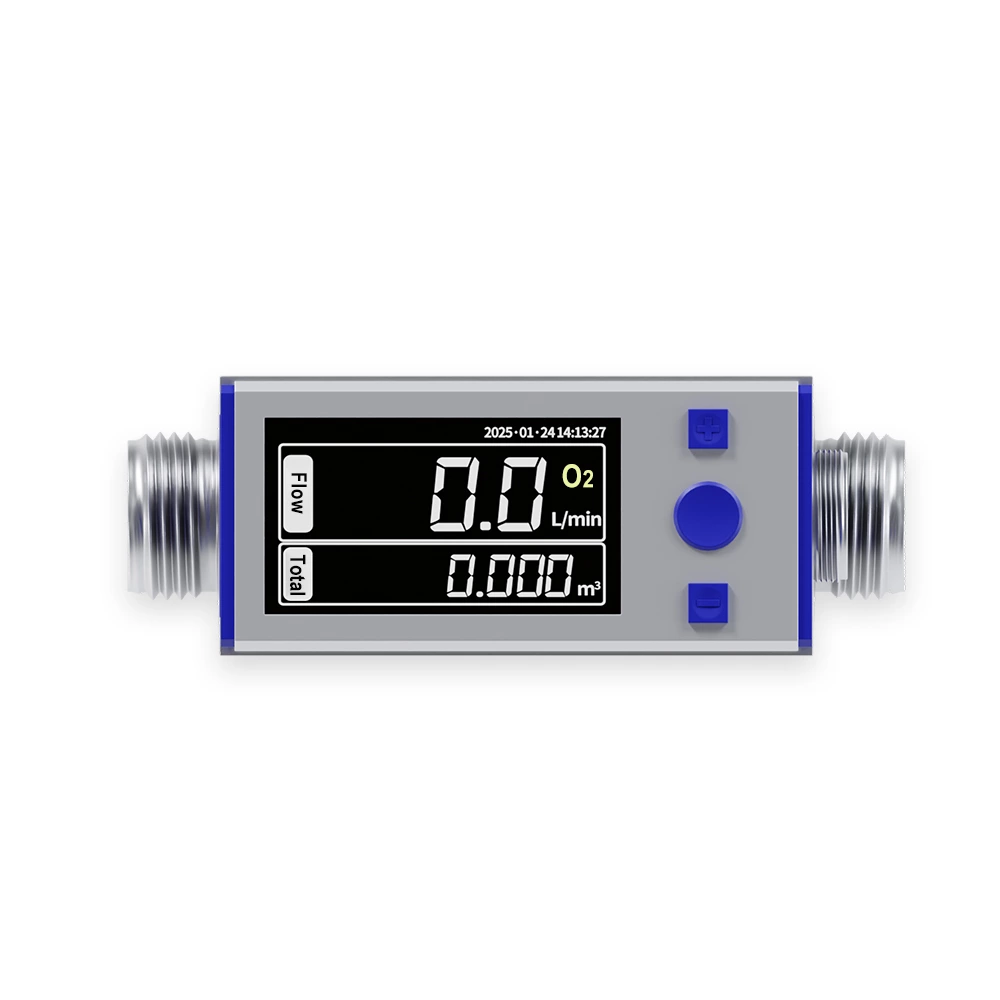
OLED Display: High-resolution OLED screen with English and Chinese menu for intuitive operation
Built-In Functions: Self-check and self-diagnostic functions for reliable operation
Flow Data Tracking: Three internal counters display forward cumulative flow, reverse cumulative flow, and total cumulative flow
Durable Liner: PEEK liner supports negative pressure applications
Remote Operation: Infrared handheld operator (38 kHz) enables remote, non-contact control
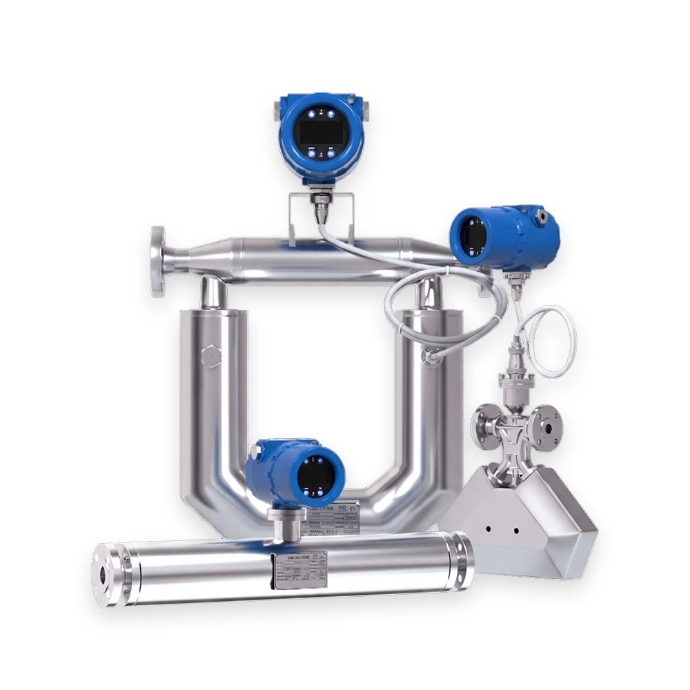
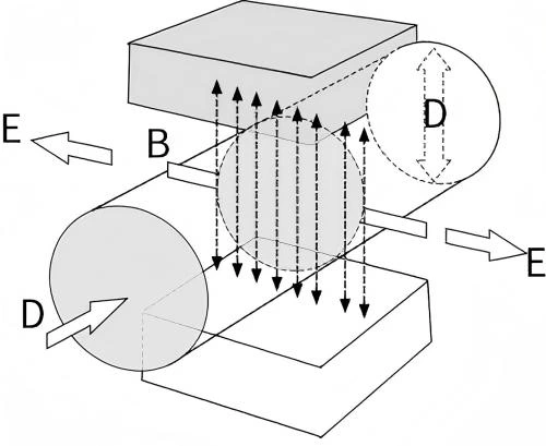
The electromagnetic flowmeter operates based on Faraday’s law of electromagnetic induction. Two electromagnetic coils at the upper and lower ends generate a magnetic field. When conductive fluid passes through the meter, an electromotive force (E) is induced between the electrodes on the flow tube wall, proportional to the flow velocity (V), magnetic flux density (B), and electrode spacing (D).
Induced Voltage Formula:
E = K × B × V × D
Where:
-
E – Induced electromotive force
-
K – Meter tube constant
-
B – Magnetic flux density
-
V – Average flow velocity
-
D – Electrode spacing
The induced voltage signal is transmitted to the converter for analog and digital processing. The instantaneous flow and totalized flow are then displayed on the converter’s screen.
Water Treatment & Supply – Municipal water and wastewater systems
Chemical & Petrochemical Industry – Conductive liquid process monitoring
Food & Beverage Industry – Flow measurement of conductive fluids in production lines
HVAC & Energy Systems – Heating, cooling, and thermal energy monitoring
Industrial Process Control – Chemical fiber, metallurgy, and paper manufacturing
Environmental Monitoring – Process monitoring and energy efficiency projects