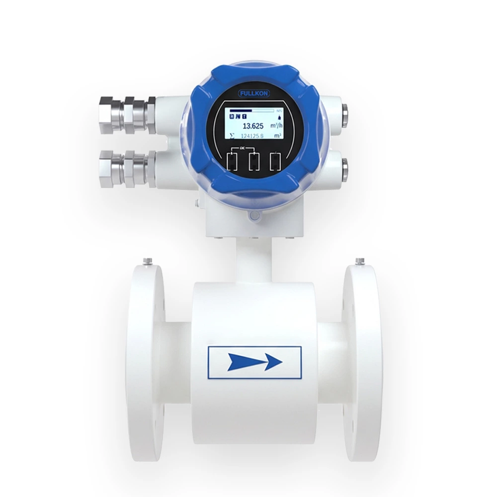
The FK-LDG-A100D Explosion-Proof Electromagnetic Flow Meter is designed based on Faraday’s Law of Electromagnetic Induction and is specially engineered for measuring the instantaneous and cumulative flow of conductive liquids in enclosed pipelines located in hazardous and explosive environments.
The flowmeter integrates robust explosion-proof protection with high-precision electromagnetic measurement technology, ensuring reliable performance in flammable industrial sites.
It supports multiple output signals for monitoring, recording and automatic process control, making it suitable for industrial automation systems.
The meter is widely used in:
Low-Frequency Square Wave Excitation
Improves zero stability and enhances anti-interference performance.
Strong Anti-Interference Capability
Reliable operation in complex industrial environments.
Bidirectional Measurement
Not affected by fluid flow direction; supports forward and reverse flow measurement.
No Moving Parts
Maintenance-free structure with long service life.
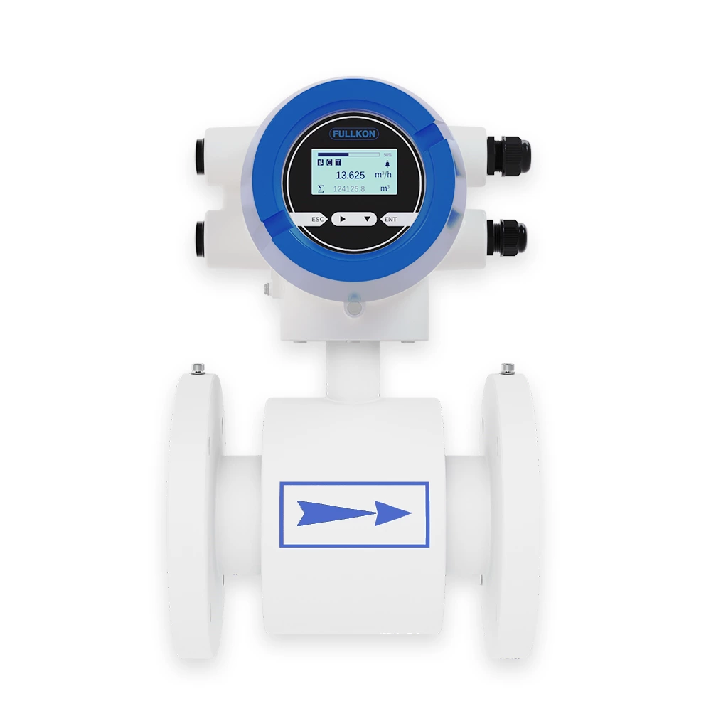
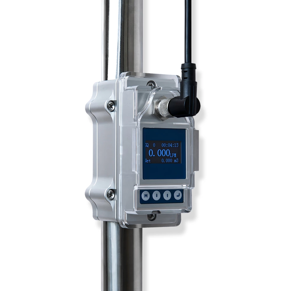
Integrated Compact Design
Easy installation and stable performance.
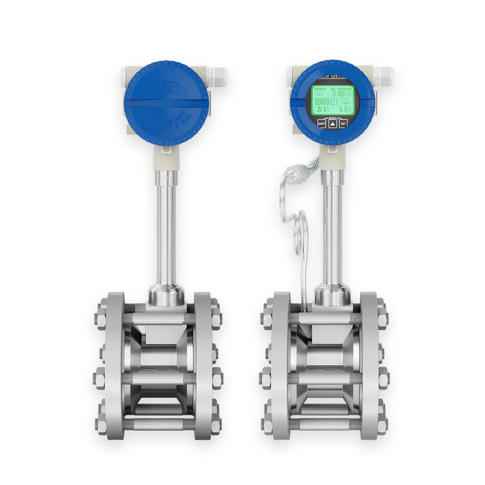
Touch Key Operation
Parameters can be configured without opening the enclosure.
Adjustable Display Orientation
The display head can be rotated for convenient reading at various installation angles.
Multi-Language Interface
Supports Chinese, English, Korean, Russian and Spanish with free switching.
Safe operation in explosive environments
Accurate and stable electromagnetic measurement
Strong anti-interference capability
Multi-signal output for automation systems
Durable industrial-grade construction
International explosion-proof compliance
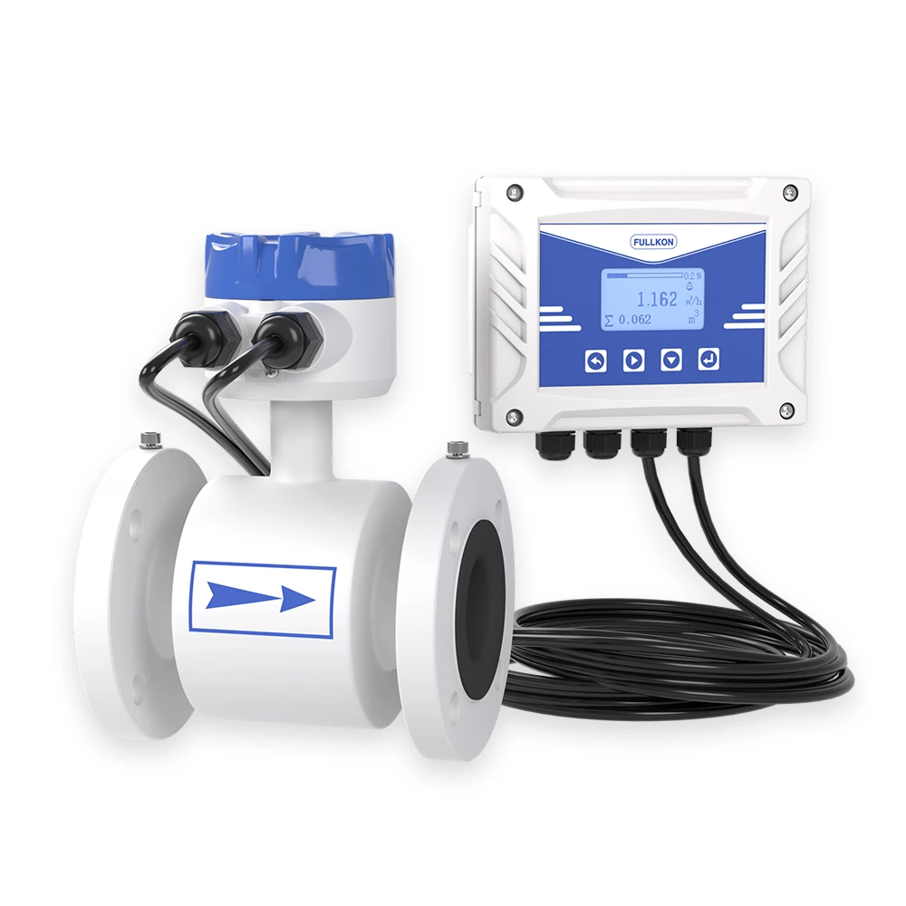
The FK-LDG-A100D operates according to Faraday’s Law of Electromagnetic Induction.
Two electromagnetic coils installed on the upper and lower sides of the measuring tube generate a constant or alternating magnetic field.
When conductive liquid flows through the magnetic field:
-
An induced electromotive force (E) is generated.
-
The induced voltage is proportional to the flow velocity.
-
Two electrodes mounted on the tube wall detect the voltage.
-
The converter processes the signal to calculate flow rate.
Induced Voltage Equation:
E = K × B × V × D
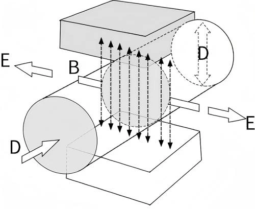
Where:
-
E – Induced electromotive force
-
K – Meter constant
-
B – Magnetic induction density
-
V – Average flow velocity
-
D – Inner diameter of measuring tube
Because the induced voltage is proportional to flow velocity, accurate flow measurement can be achieved as long as the liquid conductivity exceeds the minimum required level.
The processed signal provides:
The FK-LDG-A100D Explosion-Proof Electromagnetic Flowmeter is ideal for:
Chemical Industry
Oil & Gas & Coal Industry
Environmental Protection
Municipal Water Systems
-
Tap water measurement
-
Water treatment plants
Metallurgy & Papermaking
-
Key Advantages for Industrial Applications
-
Certified Explosion-Proof (Ex) design
-
High measurement accuracy and repeatability
-
Stable zero-point performance
-
Suitable for conductive liquids
-
Long-term reliability in hazardous environments
-
Easy commissioning and configuration
-
Designed for Hazardous Areas
The FK-LDG-A100D has passed multiple international explosion-proof certifications (Ex), making it suitable for:
-
Flammable gas environments
-
Explosive vapor areas
-
Chemical processing zones
-
Oil & gas installations
-
Hazardous industrial sites
Its explosion-proof structure ensures safe and stable operation in demanding industrial conditions.