The LUB Series Vortex Flow Meter is a velocity-type flowmeter designed based on the Kármán vortex shedding principle for flow measurement and control of gases, steam, and liquids in closed industrial pipelines.
By installing a triangular bluff body in the flow path, the meter generates alternating vortices downstream as the fluid passes through. The vortex shedding frequency is directly proportional to the flow velocity. A high-sensitivity piezoelectric sensor detects the vortex frequency and converts it into an electrical signal, which is processed to accurately calculate instantaneous and total volumetric flow.
Depending on configuration, the LUB series also supports temperature and pressure measurement, with multiple output and communication options including pulse output, 4–20 mA, RS485 (Modbus RTU), HART, and optional GPRS remote transmission for IoT applications.
With a robust structure, no moving parts, and stable performance, the LUB vortex flow meter is minimally affected by fluid properties and is widely used in a variety of industrial flow measurement systems.
No Moving Parts
Solid structure with no mechanical wear, ensuring high reliability and long service life.
Linear Frequency Output
Flow signal is a pulse frequency linearly proportional to actual flow rate, with no zero drift and stable performance.
Multiple Structural Types
Available in inline (flanged) and insertion-type configurations.
High Accuracy & Wide Range
Liquids: ±1.0% of reading
Gases: ±1.0% to ±1.5% of reading
Low Pressure Loss
Pressure loss is approximately 1/4 to 1/2 of an orifice flowmeter, improving energy efficiency.
Flexible Installation
Can be installed horizontally, vertically, or at an inclined angle according to site conditions.
Strong Anti-Interference Design
Multiple circuit protection designs with strong surge resistance.
High-Precision Sensor
Piezoelectric crystal vortex sensor with stable signal output.
Sensor housing made of 316L stainless steel, offering excellent corrosion resistance to alkaline solutions and most organic and inorganic acids.
Long-Life Lithium Battery
Built-in 3.6V high-energy-density lithium battery, typical service life of 1–2 years.
Wide Temperature Adaptability
Suitable for high and low temperature applications, environmentally friendly design.
Stable Meter Factor
Within a certain Reynolds number range, the meter factor is independent of fluid temperature, pressure, and composition. In most cases, recalibration is not required after component replacement.
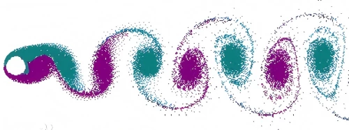
When a fluid flows past the triangular vortex shedder installed in the pipe, alternating vortices are generated on both sides of the shedder. These vortices, known as Kármán vortices, form a regular vortex street downstream.
The frequency of vortex shedding is proportional to the flow velocity within a specific Reynolds number range. A high-sensitivity sensor detects the vortex frequency, and the signal is processed by an internal processor to calculate the volumetric flow rate.
Flow calculation relationship:
-
Q = Volumetric flow rate (m³/h)
-
F = Vortex frequency (Hz)
-
K = Flow coefficient (calibration factor), obtained through standard flow calibration
The K-factor is typically determined by calibration and remains stable during operation.
Classification by Function
-
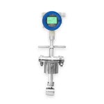
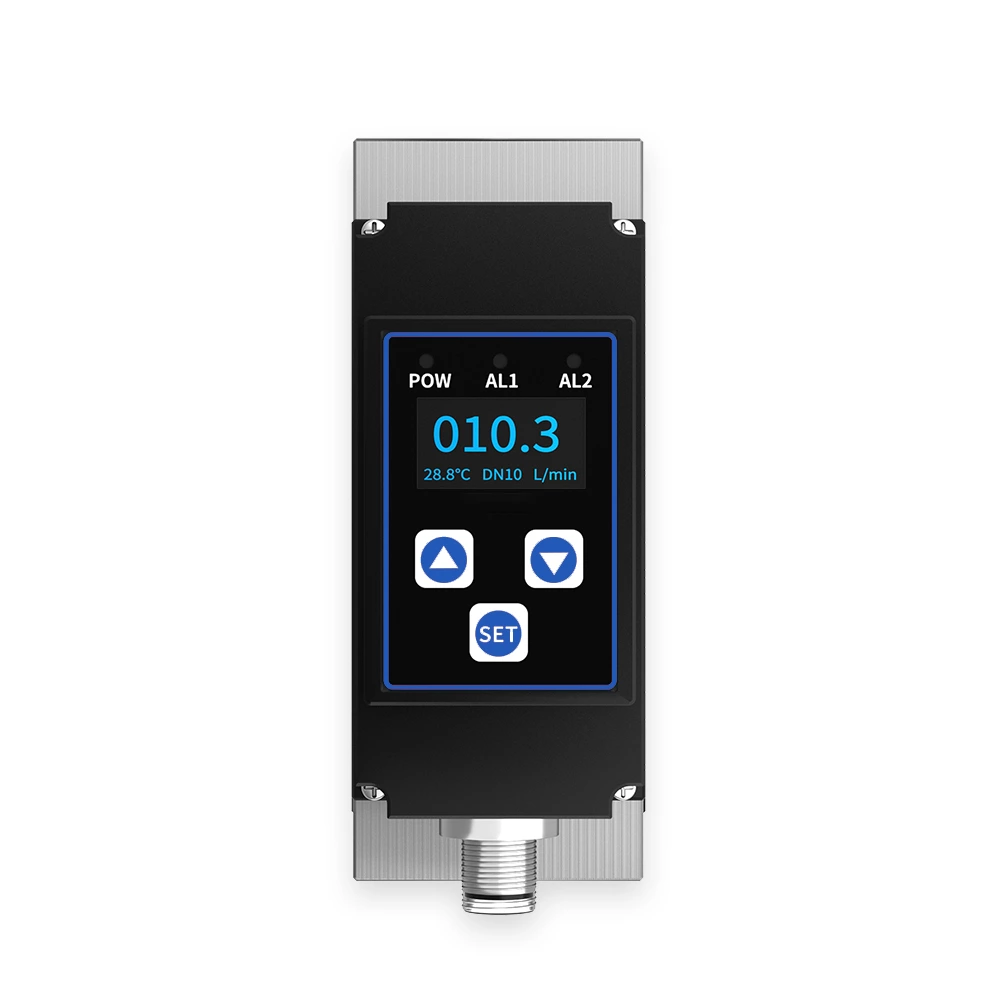
Standard Local Display Vortex Flowmeter
Integrates the vortex flow sensor and flow totalizer into a single unit. Its main performance indicators reach the leading domestic level, making it an ideal instrument for petroleum, chemical, electrical, light industry, and power heating industries.
-
Temperature & Pressure Compensated Vortex Flowmeter
Combines the vortex flow sensor and flow totalizer with temperature and pressure compensation functions. Its main performance indicators are at the leading domestic level, suitable for petroleum, chemical, electrical, light industry, and power heating industries.
-
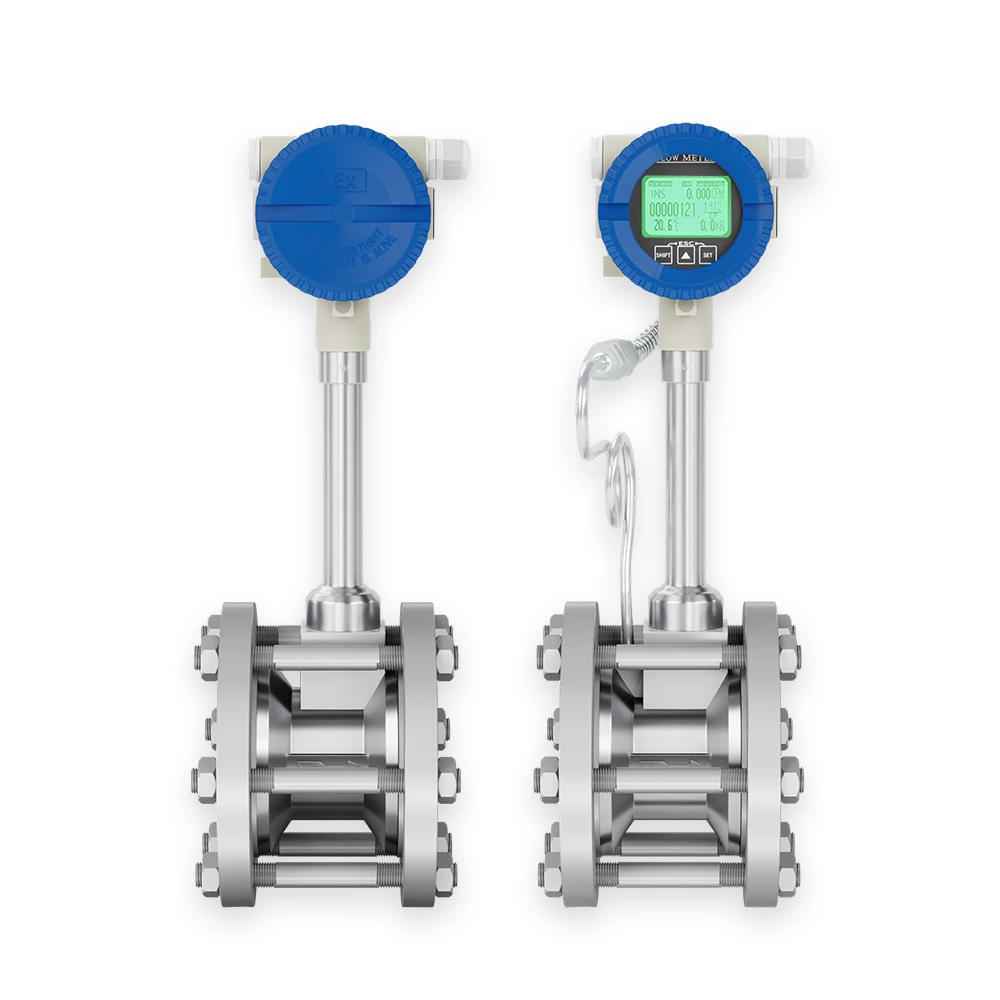
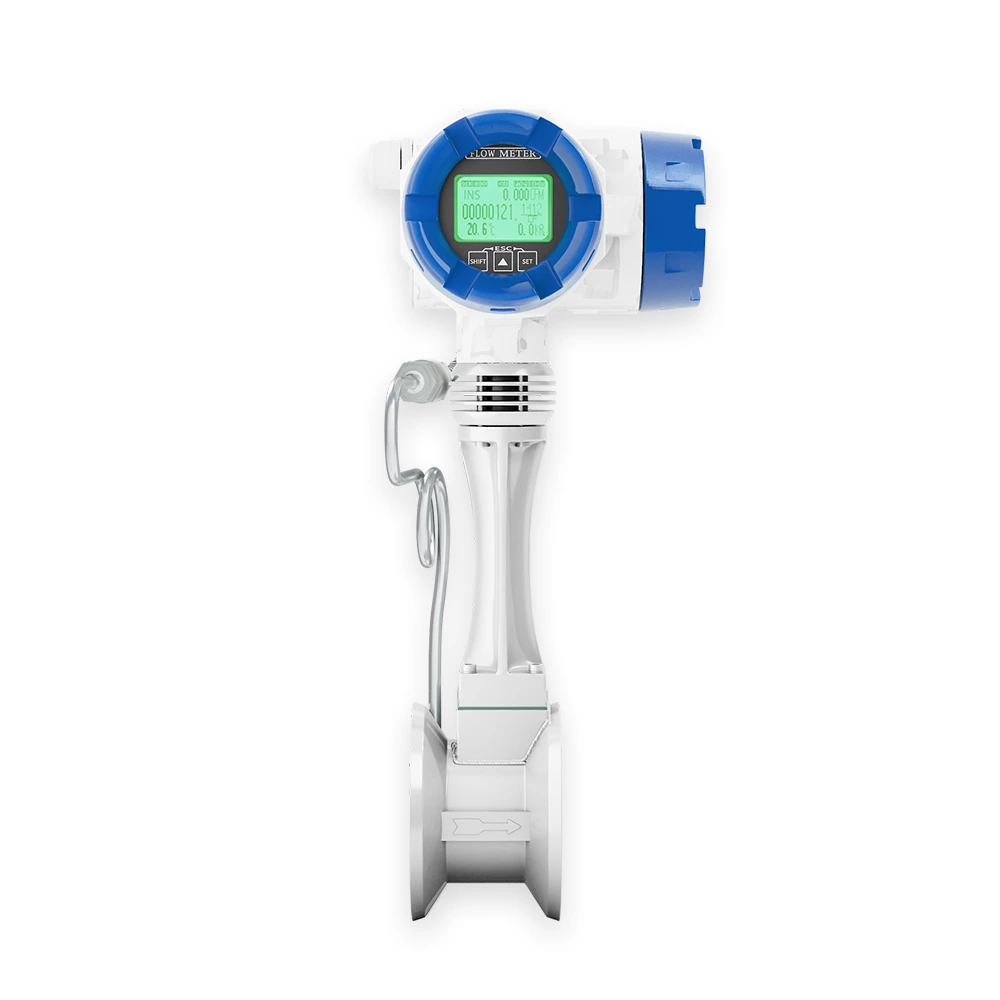
Remote/Separated Vortex Flowmeter
The vortex flow sensor and flow totalizer are installed separately, providing remote display functionality. It allows high installation with low-level display, facilitating meter reading in elevated installations.
Classification by Installation Method
-
Wafer / Clamp Type Vortex Flowmeter
-
Flanged Vortex Flowmeter
-
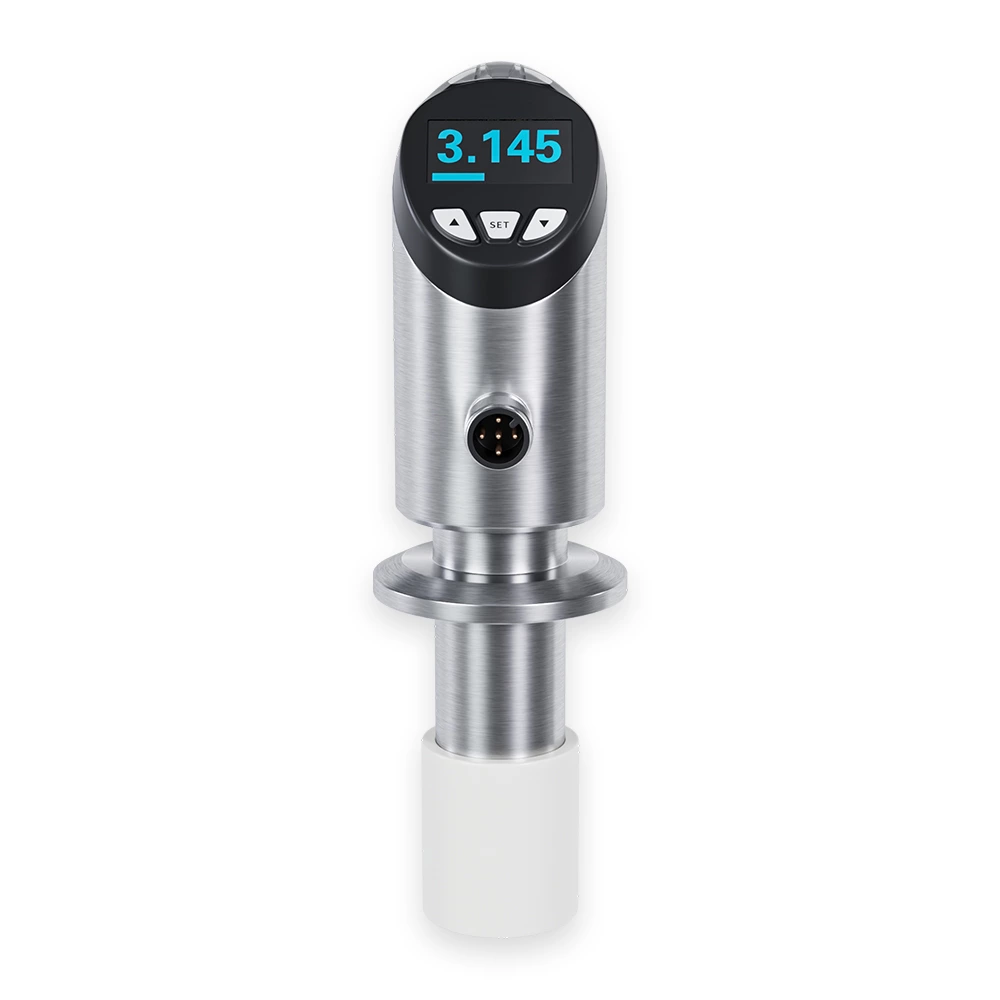
Simple / Ball Valve Insertion Vortex Flowmeter
-
Threaded Vortex Flowmeter
-
Clamp Connection Vortex Flowmeter
-
Separated / Remote Vortex Flowmeter
-
Other Special Designs: Customization available upon agreement with the supplier
Heating and district heating systems
Gas supply systems
Chemical industry
Environmental protection projects
Metallurgy and steel plants
Textile industry
Pharmaceutical industry
Paper and pulp industry
Drainage and water treatment
Steam measurement (saturated steam & superheated steam)
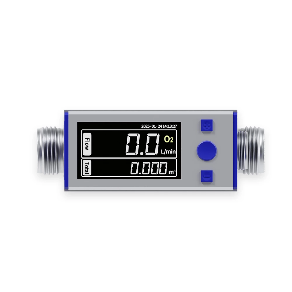
Compressed air and industrial gases
(oxygen, nitrogen, hydrogen, natural gas, coal gas, etc.)
Liquids such as water, gasoline, alcohol, and benzene-based fluids