
-
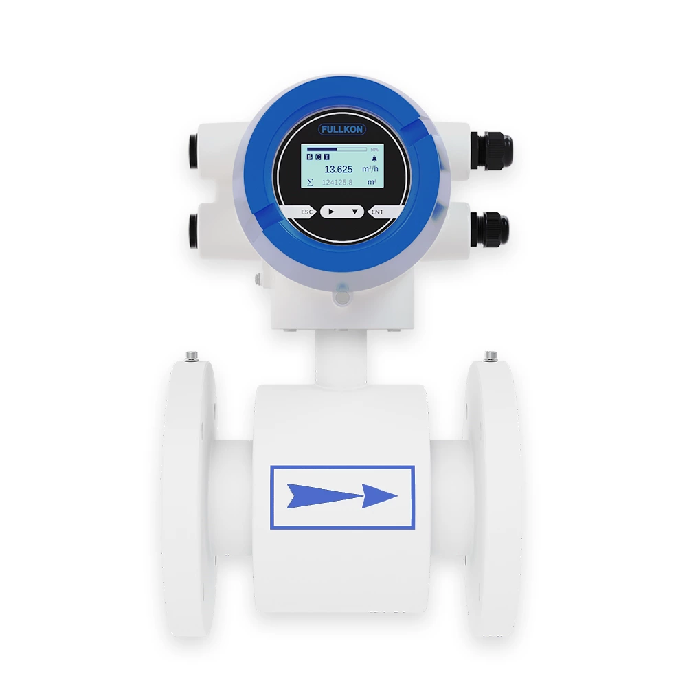
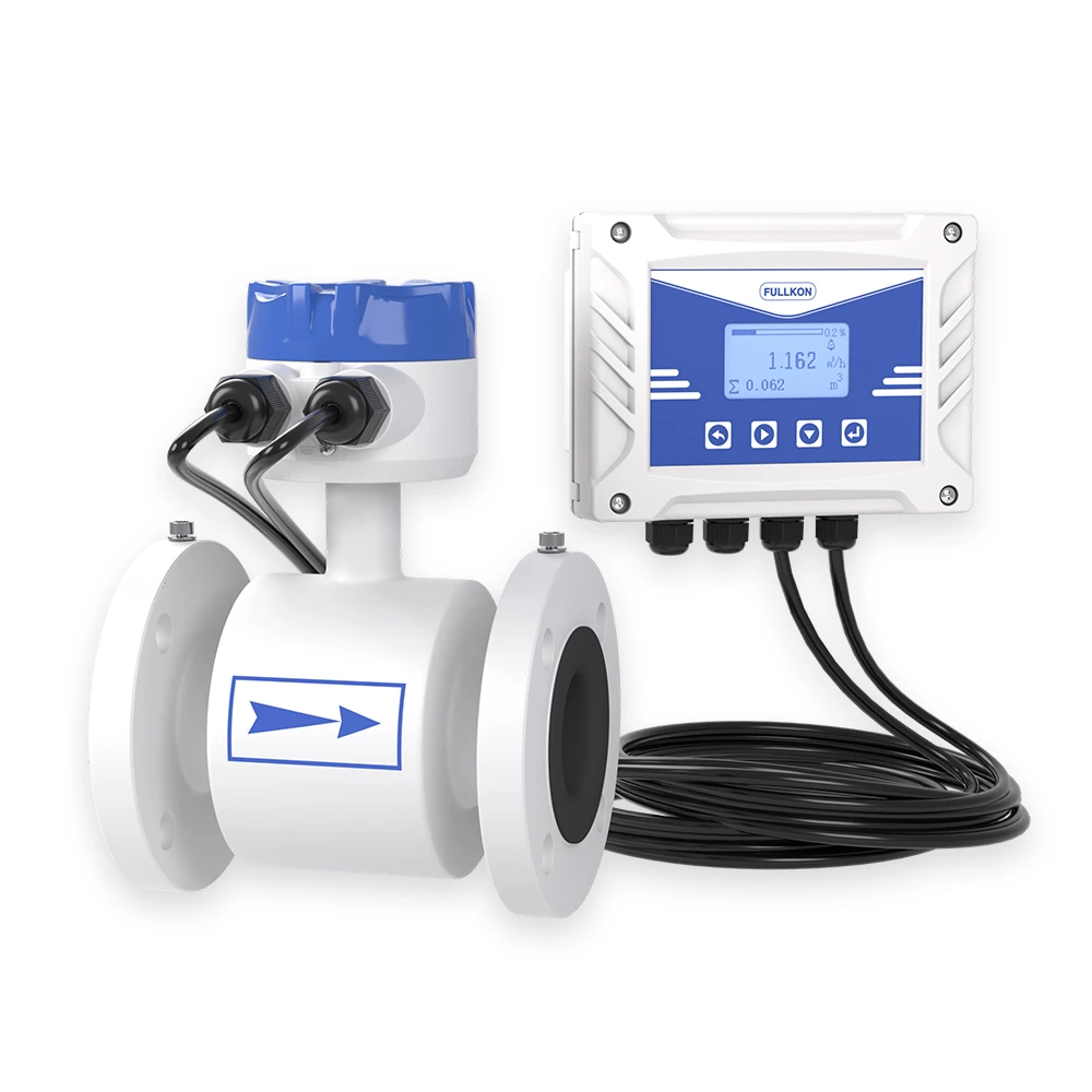
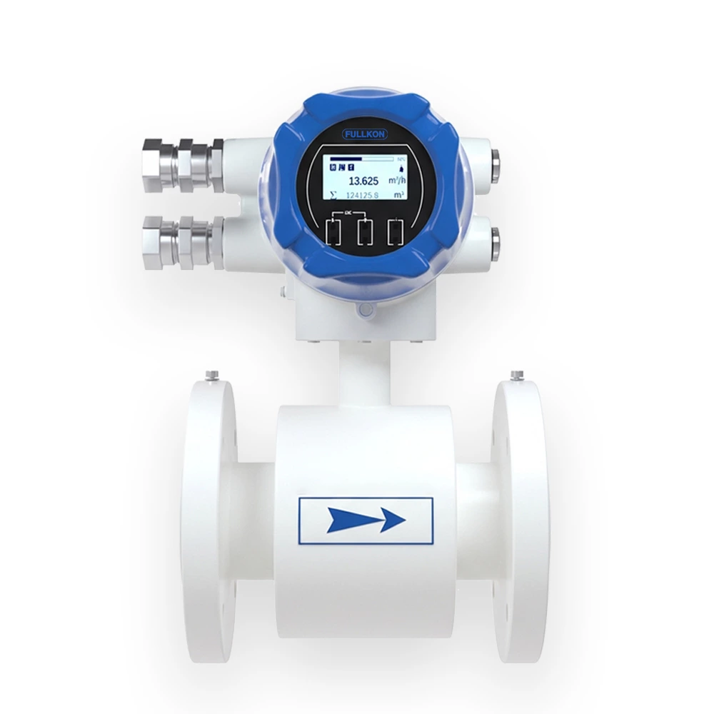
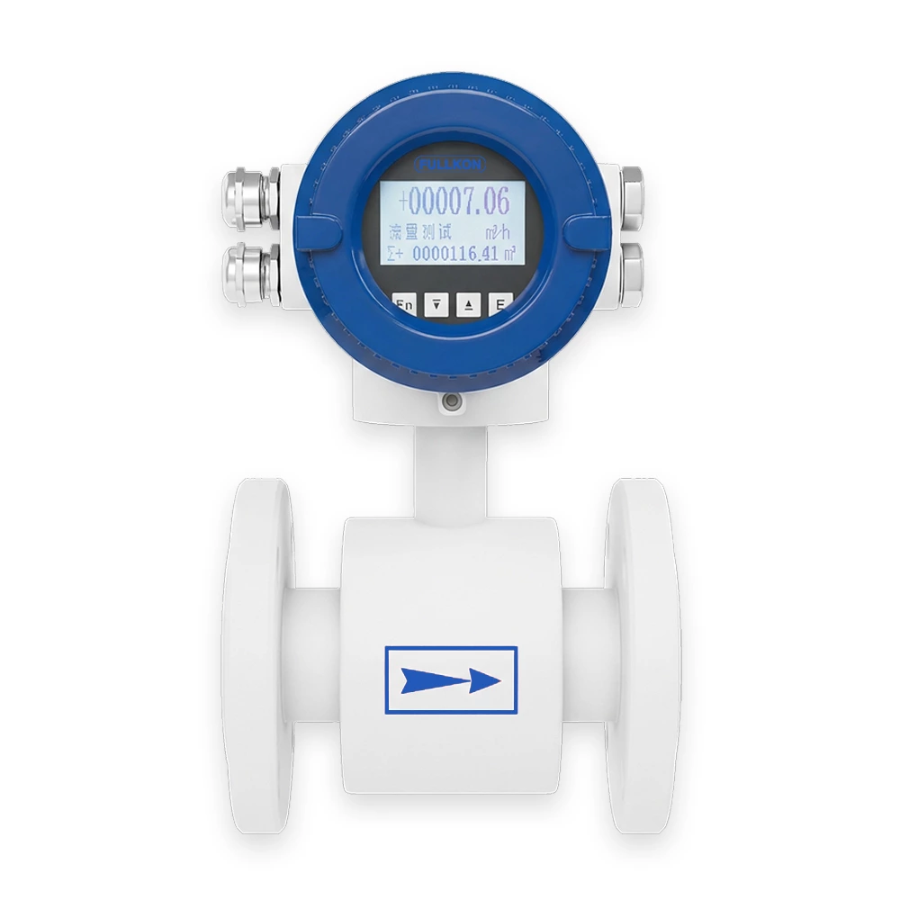
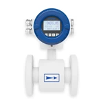
Measuring principle
The slurry electromagnetic flowmeter operates according to Faraday’s Law of Electromagnetic Induction.
Two electromagnetic coils generate a magnetic field perpendicular to the flow direction. When a conductive slurry flows through the magnetic field, an induced electromotive force (E) is generated between two electrodes installed on the tube wall.
The induced voltage is proportional to:
-
Flow velocity (V)
-
Magnetic flux density (B)
-
Electrode spacing (D)
The relationship is expressed as:
E = K × B × V × D
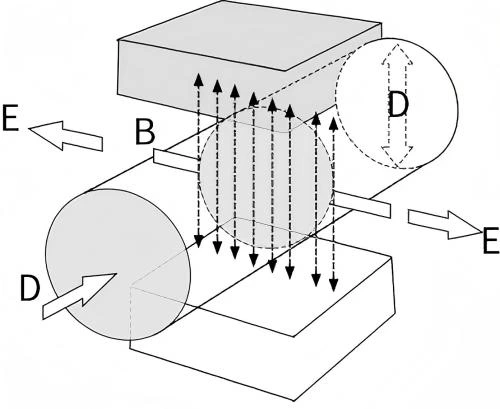
Where:
-
E – Induced electromotive force
-
K – Meter tube constant
-
B – Magnetic flux density
-
V – Average flow velocity
-
D – Electrode spacing
The induced voltage signal is processed through analog and digital circuits, and the converter displays both instantaneous flow and totalized flow.
The measured medium must have electrical conductivity above the minimum threshold specified in the technical parameters.
-
Key Technologies for Slurry Measurement
To ensure accurate slurry flow measurement in harsh environments, the meter incorporates advanced targeted technologies:
Hybrid Low- and High-Frequency Excitation Technology
-
Combines low-frequency and high-frequency excitation signals
-
Suppresses low-frequency baseline drift
-
Reduces high-frequency particle noise
-
High-frequency excitation up to 75Hz enables rapid data sampling
-
Multi-parameter software filters eliminate interference
This design significantly improves stability and reliability in high solid slurry conditions.
Advanced Slurry Noise Suppression
Slurry flow generates at least five different types of noise with distinct characteristics. The system:
-
Establishes a slurry flow signal model
-
Applies multi-stage digital filtering
-
Uses wavelet transform processing
-
Implements dynamic approximation algorithms
-
Reconstructs adaptive slurry flow signal models
This enables accurate extraction of the true flow signal even in low signal-to-noise ratio environments.
Enhanced Signal-to-Noise Ratio (SNR)
Optimized sensor structure and electrode placement combined with advanced signal processing algorithms:
-
Improve signal stability
-
Reduce turbulence interference
-
Minimize deviation caused by entrained gas
-
Ensure reliable measurement under complex slurry conditions
Wear-Resistant Construction
Designed for abrasive slurry applications such as:
-
Coal-water slurry
-
Mining ore slurry
-
Industrial sludge
Optional wear-resistant materials:
-
Polyurethane (PU) lining
-
Tungsten carbide reinforced electrodes
This extends service life and reduces maintenance frequency in high-abrasion environments.