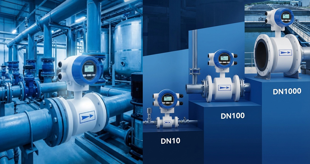
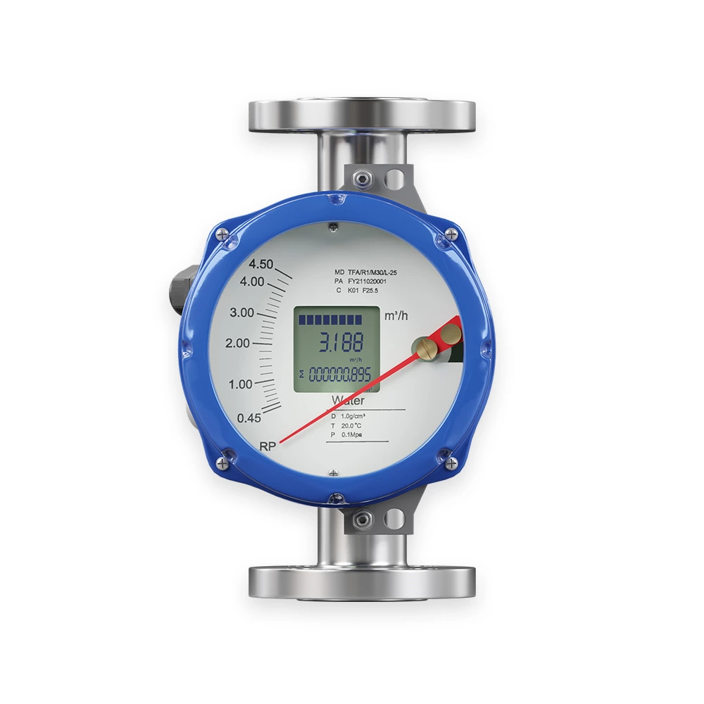
The EMF Series Electromagnetic Flow Meter is designed based on Faraday’s electromagnetic induction principle to directly measure the flow of conductive liquids in closed pipelines. It provides cumulative flow measurement and outputs standard current, pulse, and RS485 digital signals for recording, control, and regulation. Factory parameters are pre-set according to order specifications, minimizing user setup time. The meter is suitable for applications where liquid conductivity meets the minimum design requirement (see Technical Specifications).
The instrument ensures accurate flow measurement in industries such as water supply, chemical processing, coal, environmental protection, textile, metallurgy, and paper manufacturing. Online conductivity should be used for calibration, as offline measurements can be affected by dissolved gases, leading to higher conductivity readings.
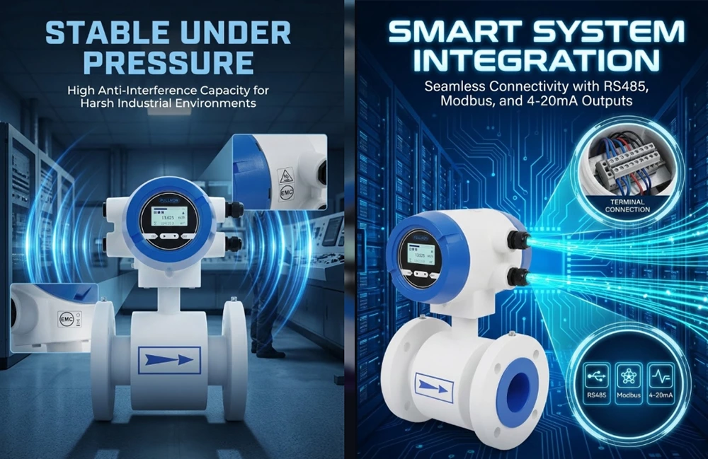
High measurement reliability, accuracy, and stability.
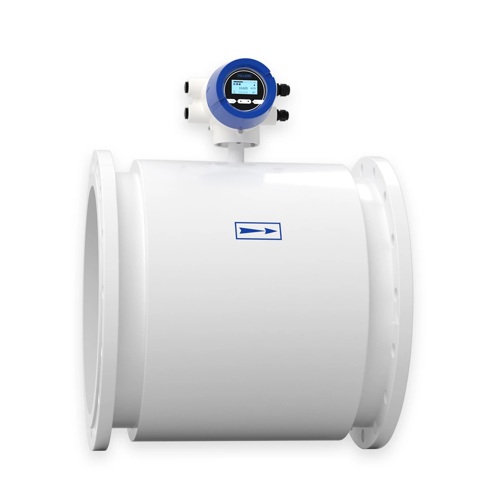
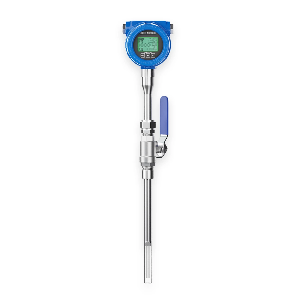
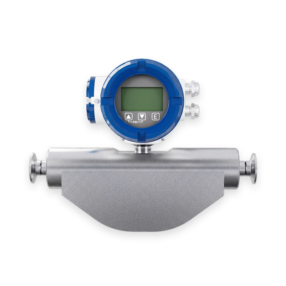
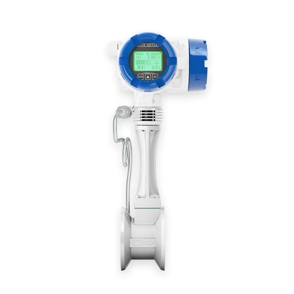
Integral structure with no moving parts; easy installation and maintenance-free.
RS485 communication interface with standard Modbus RTU protocol.
Bidirectional flow measurement capability.
Advanced low-frequency square wave excitation for stable zero point and strong anti-interference.
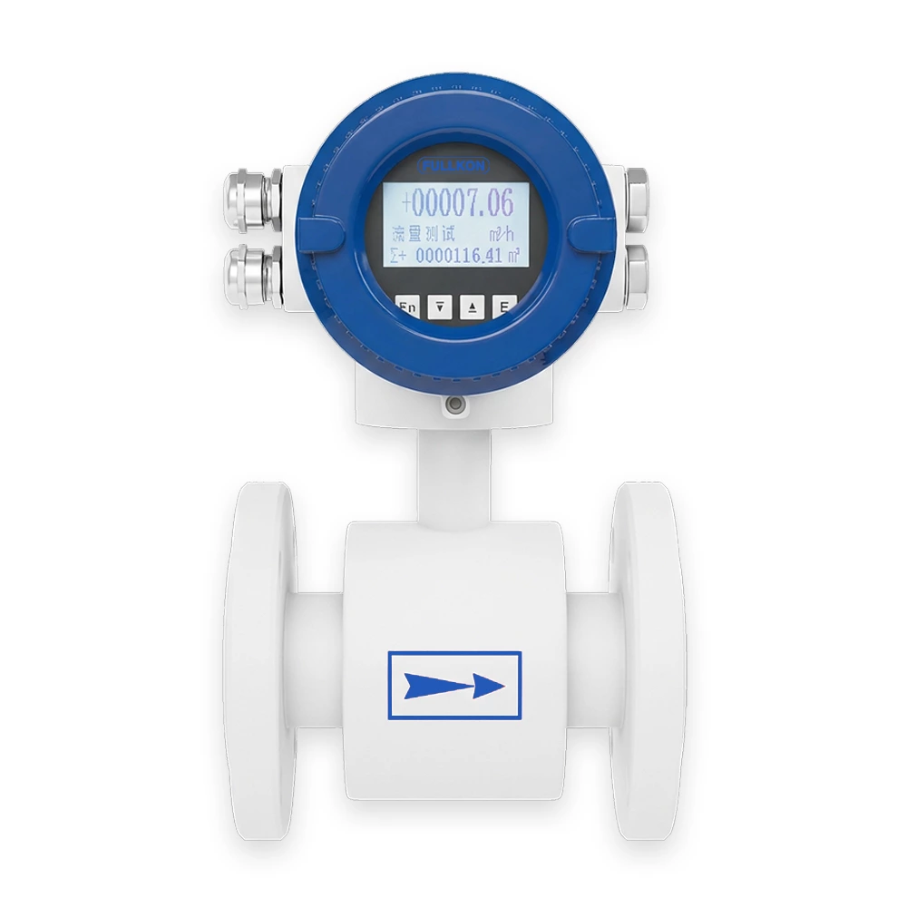
Adjustable display orientation for convenient reading.
Built-in Chinese/English interface with free switching.
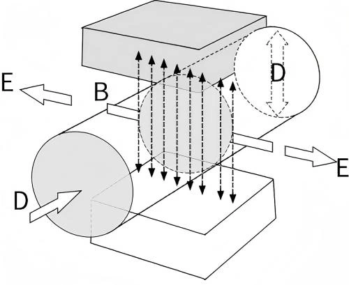
The electromagnetic flow meter uses advanced low-frequency square wave excitation. According to Faraday’s law of electromagnetic induction, two coils located at the top and bottom of the measurement tube generate a constant or alternating magnetic field. When conductive liquid flows through the sensor, an induced voltage is generated between the two electrodes mounted on the tube walls. The induced voltage is proportional to the flow velocity, magnetic field strength, and pipe diameter:
Where:
-
E – Induced voltage
-
K – Instrument constant
-
B – Magnetic flux density
-
V – Average flow velocity in the measurement tube
-
D – Internal diameter of the measurement tube
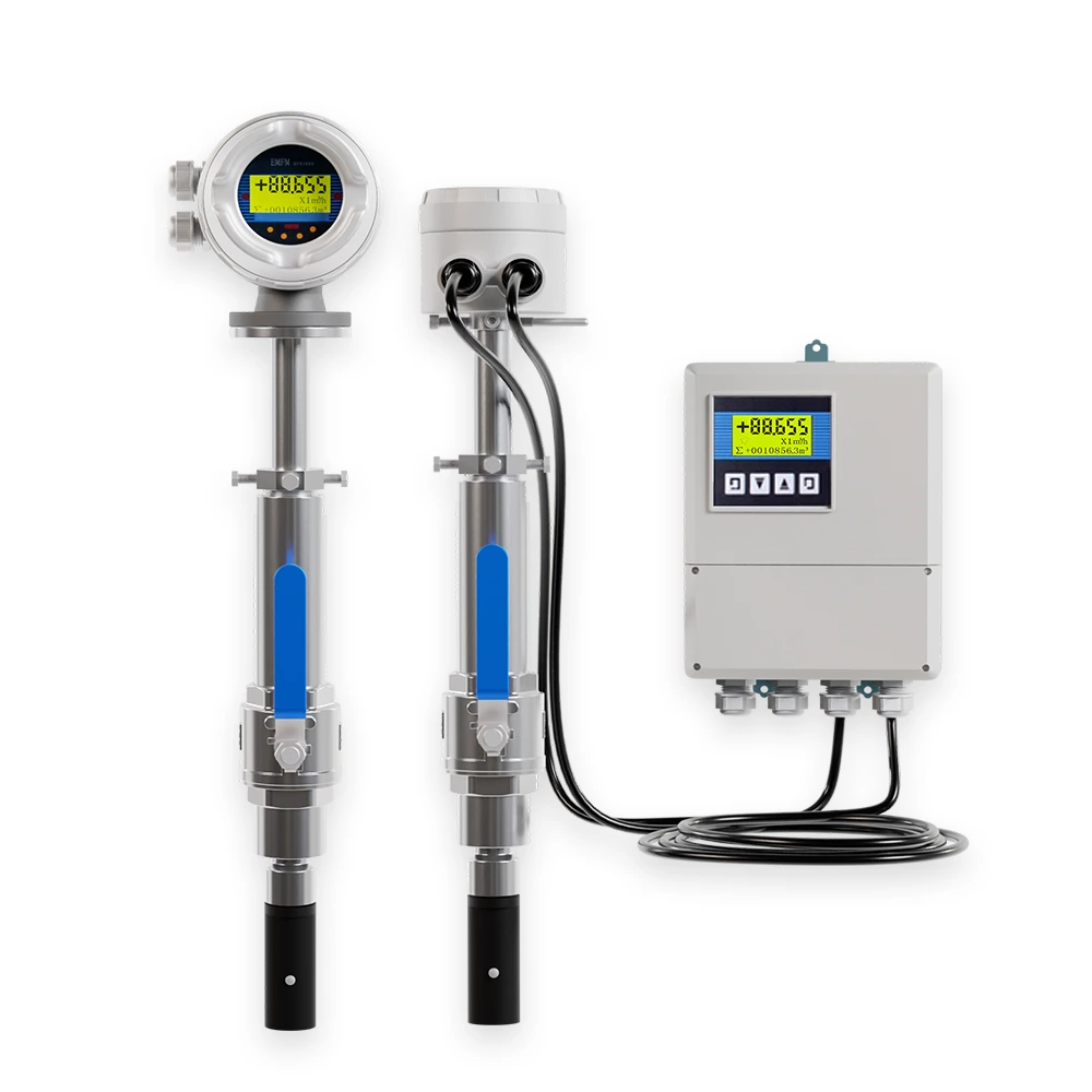
The induced voltage is detected by electrodes and transmitted via cable to the converter. After analog and digital signal processing, instantaneous and cumulative flow are displayed on the converter screen. Flow measurement is independent of flow direction, ensuring accurate bidirectional readings.
Municipal water supply and wastewater treatment
Chemical process industry
Coal and energy sector
Environmental protection systems
Textile and light industry
Metallurgical processes
Paper and pulp industry