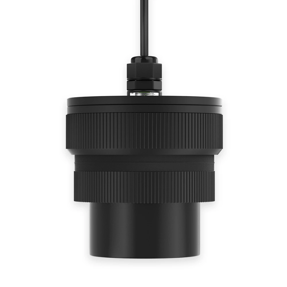
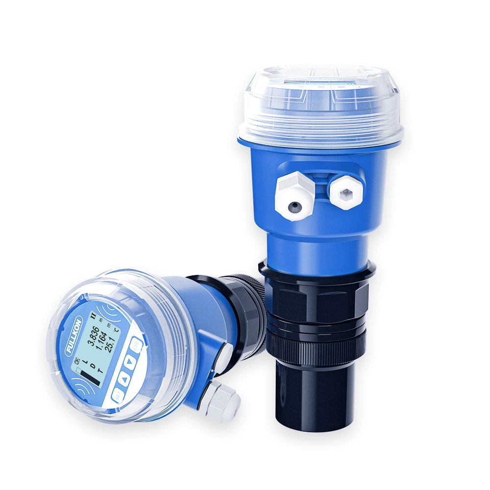
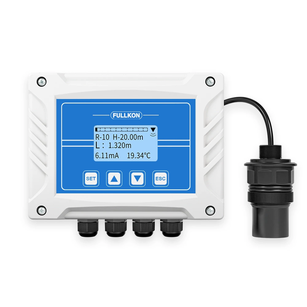
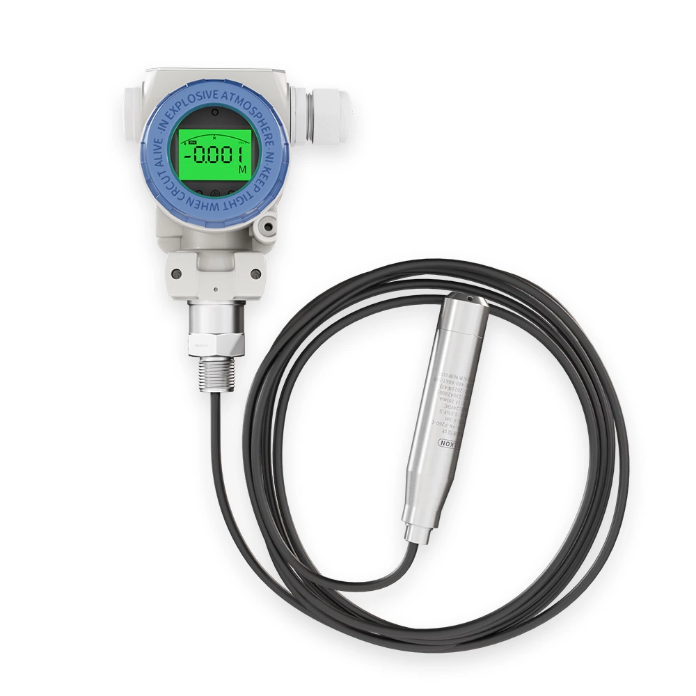
The low power ultrasonic level transmitter is a non-contact level measurement instrument based on ultrasonic distance measurement technology. It adopts advanced microprocessor technology combined with a low power design, enabling accurate and stable measurement of liquid or material surface levels.
By transmitting ultrasonic pulses toward the target surface and analyzing the reflected signal, the sensor continuously calculates the distance between the transducer and the liquid surface. This makes it suitable for a wide range of applications, including drainage systems, water conservancy, hydrology, municipal utilities, environmental protection, water management, and industrial level measurement.
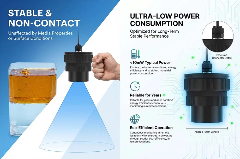
Non-contact measurement, no direct contact with the liquid
Measurement performance not affected by liquid conductivity, density, or chemical properties
High accuracy and high resolution with minimal measurement error
Low power consumption design, suitable for long-term continuous operation
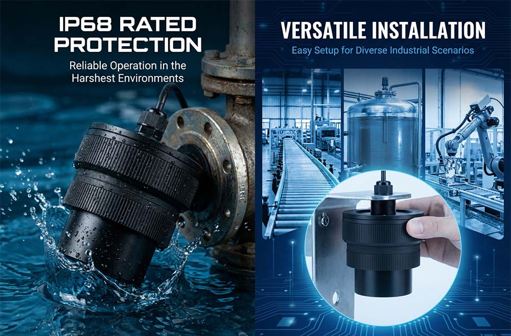
Simple installation and easy commissioning
IP68 protection rating, ensuring reliable operation in harsh environments
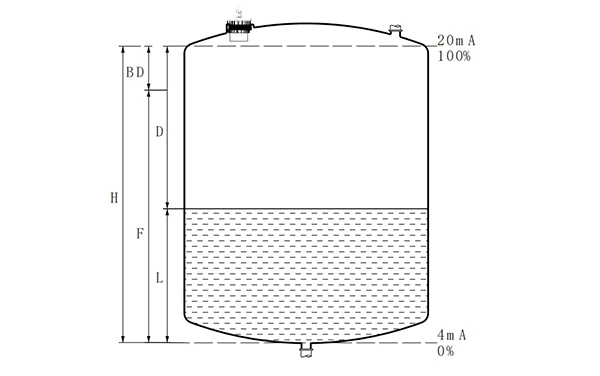
The ultrasonic level transmitter operates based on the propagation and reflection of ultrasonic waves in air.
When the ultrasonic transducer emits an ultrasonic pulse toward the liquid surface, the sound wave is reflected back upon reaching the surface. The reflected signal is received by the same transducer and converted into an electrical signal. By measuring the time difference between transmission and reception, and using the known speed of sound in air, the distance between the sensor and the liquid surface is calculated.
Based on the installation height and the measured distance, the liquid level is determined accurately.
Key parameters in measurement:
The low power ultrasonic level transmitter is widely used for liquid and material level measurement in the following fields:
Drainage Systems
Sewage pipelines, pump stations, and manholes
Water Conservancy & Hydrology
Rivers, lakes, reservoirs, and water level monitoring stations
Municipal Utilities
Urban water supply, wastewater treatment plants, and rainwater monitoring
Environmental Protection
Monitoring water levels in environmental management systems
Water Management
Reservoirs, channels, and storage tanks
Industrial Applications
Liquid level measurement in industrial tanks, vessels, and containers