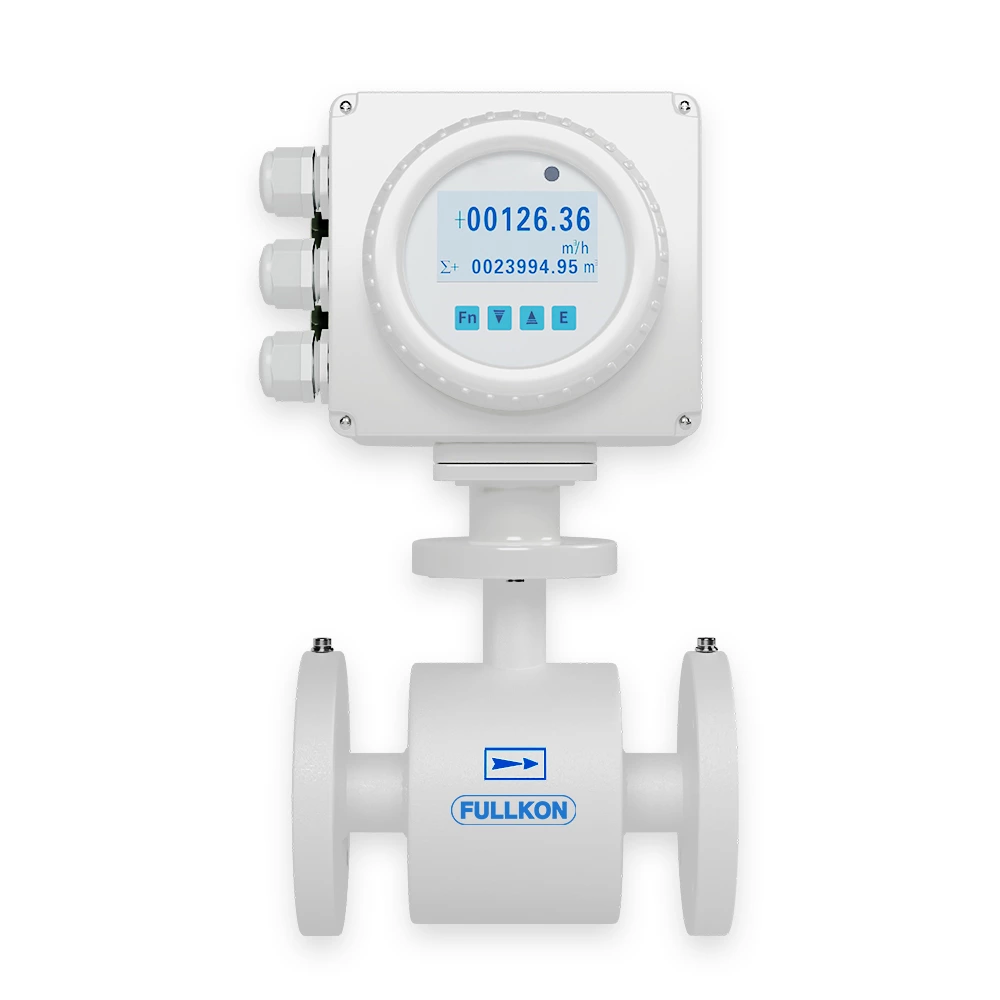
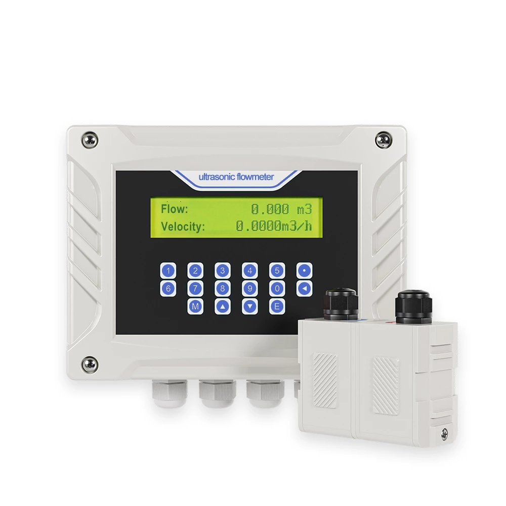
The FMC240 Electromagnetic Flow Meter uses Faraday’s law of electromagnetic induction to measure the volumetric flow rate of electrically conductive fluids. As conductive liquid passes through a magnetic field generated within the meter, the induced voltage proportional to flow velocity is detected by electrodes and converted into a flow signal. The FMC240 supports bidirectional measurement and outputs standard analog (4-20 mA), pulse/frequency signals as well as digital RS485 communication for integration with PLC or SCADA systems.
With nominal diameters from DN15 to DN1000 and multiple lining and electrode material options, this flow meter is adaptable to a broad range of conductive liquids, including water, wastewater, slurries, acids and alkalis. Pre-engineered configurations ensure ease of installation with minimal commissioning.
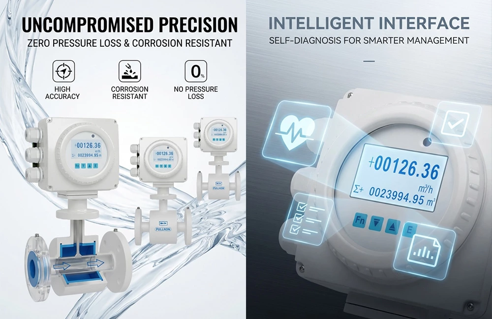
Precision Measurement: ±0.5% full scale accuracy for high-confidence readings.
Multiple Signal Outputs: 4–20 mA analog, pulse/frequency and RS485 digital communication.
Wide Diameter Range: Available DN15 to DN1000 for diverse piping systems.
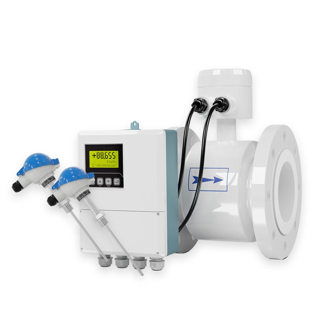
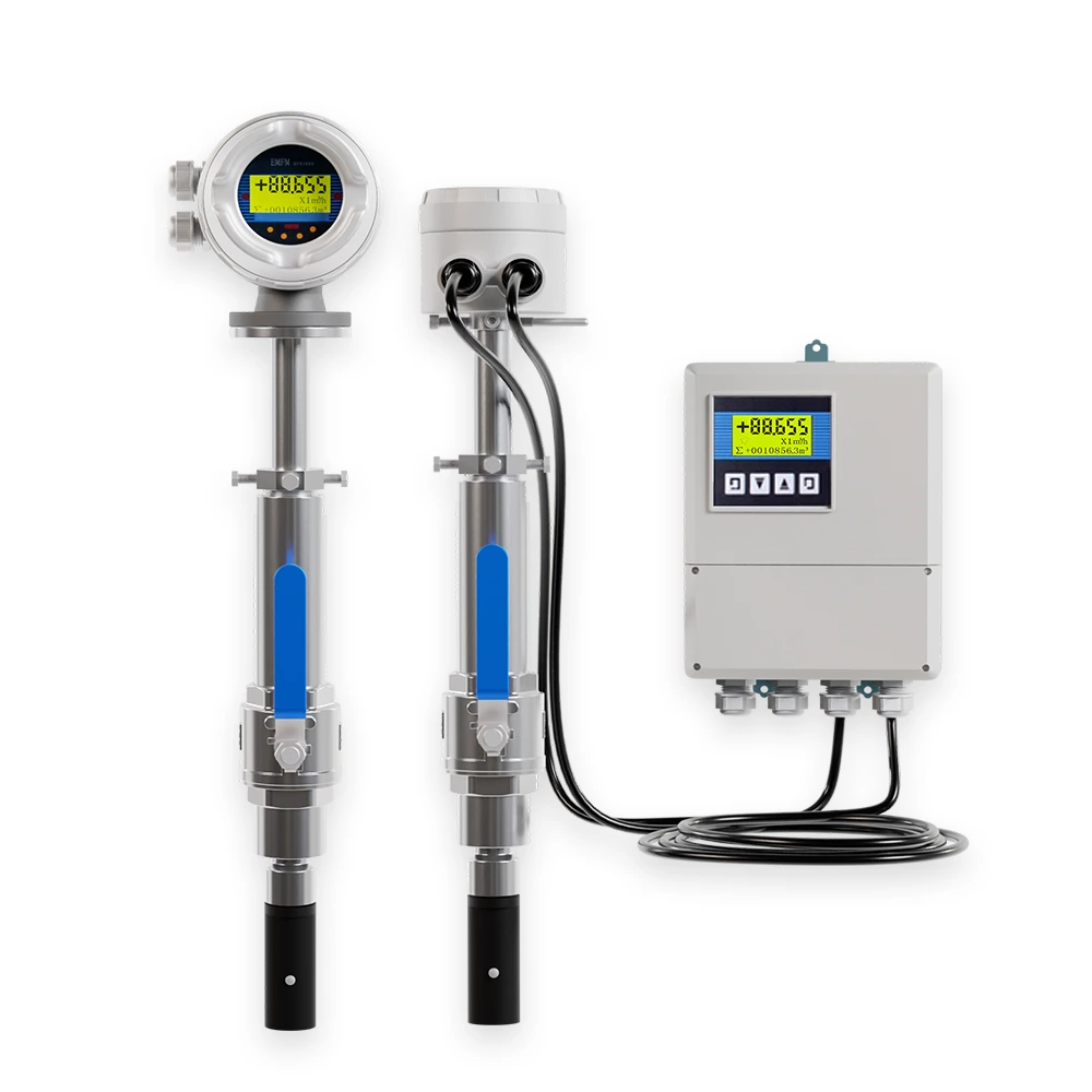
Flexible Construction: Choose compact or remote converter installation.
Corrosion-resistant Materials: Liner options (Neoprene, PU, PTFE, FEP, PFA) and electrode materials (316L SS, Hastelloy, Ti, Ta, Pt).
Robust Protection: IP65 for converter and IP68 for sensor (remote type) enables reliable use in harsh environments.
No Moving Parts: Magnetically induced measurement offers long-term stability with negligible pressure loss.
Bidirectional flow detection: Measures forward and reverse flow without orientation restrictions.
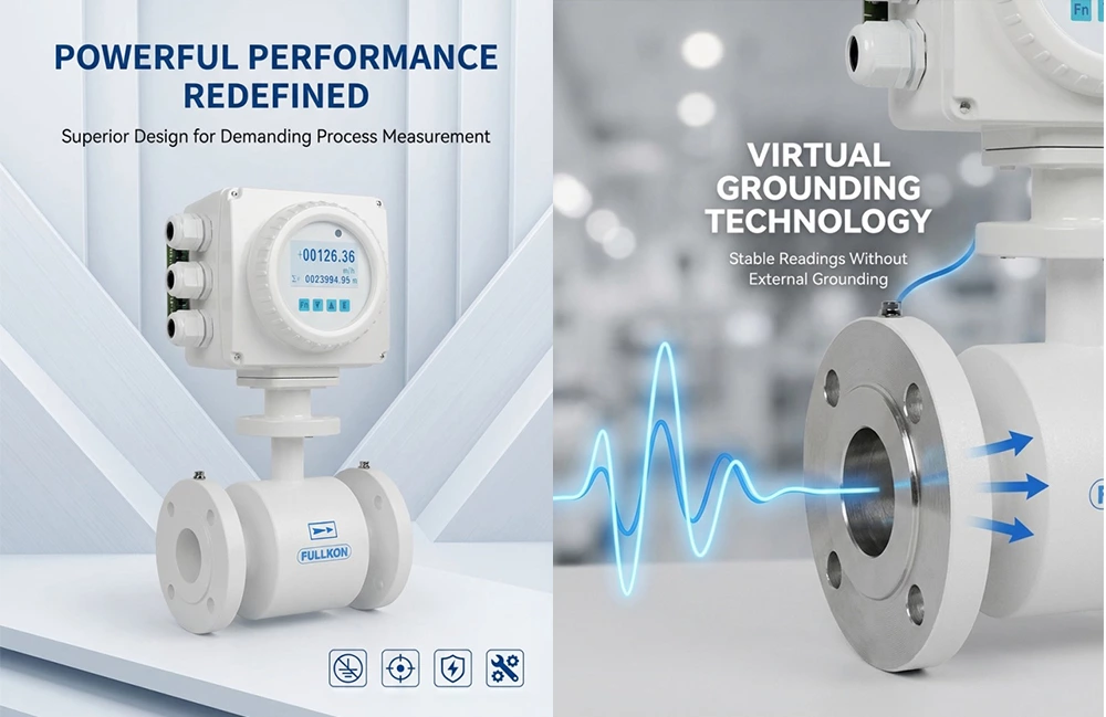
Stable output: Strong anti-interference performance and stable readings even under poor grounding.
Wide operating temperature: Depending on materials, accommodates medium temperatures up to ~120 °C (higher with specific liners).
Lightning protection capability: Suitable for use in environments prone to electrical disturbances
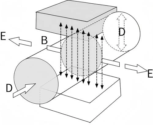
The operating principle of electromagnetic flowmeter is Faraday's law of electromagnetic induction. The two electromagnetic coils at the upper and lower ends as shown in Figure 3 generate a constant or alternating magnetic field. When the conductive medium flows through the electromagnetic flowmeter, the induced electromotive force (E) can be detected between the left and right electrodes on the wall of the flowmeter tube.
The induced electromotive force (voltage) is proportional to the velocity (V) of the conducive flow, the density of the magnetic field(B), and the length of the conductor(D). The volumetric flow can be determined by calculation, and the formula of induced electromotive force(induced emf voltage)for calculation is:
E=K×B×V×D
Where: E-Induced electromotive force
K-Meter Tube Constant
B-Magnetic Flux Density
V-Average Flow Velocity
D-Electrode Spacing
When measuring the volumetric flow, conductive flow passes through a magnetic field that is perpendicular to the flow direction. This induces an electric potential proportional to the average flow velocity. Therefore, the measured fluid must have an electrical conductivity higher than the minimum threshold of 5μs/cm. [In theory, an electromagnetic flowmeter can measure conductive media with conductivity
exceeding 5μs/cm. However, in actual measurements, it is supposed to be applied where the measured medium's conductivity is at least 30μs/cm (one to two units≥the theoretical limit). Additionally, the conductivity value must be based on online measured conductivity value].
The induced voltage signal is detected by two electrodes, and transmitted to the converter via coils. After a series of analog and digital signal processing, the totalized flow and instantaneous flow are displayed on the converter’s screen.
The FMC240 is suitable for flow measurement and control in a wide range of industries including:
Water supply and wastewater treatment – accurate monitoring of clean and wastewater streams.
Chemical processing – measurement of conductive chemicals, acids and alkalis.
Environmental systems – integration with SCADA/automation for remote monitoring.
Industrial utilities – plant water, cooling circuits and process films.
Food & beverage (sanitary or adapted versions available) – precise flow measurement in production lines.